Travelling grate/
Pulsating grate Drive
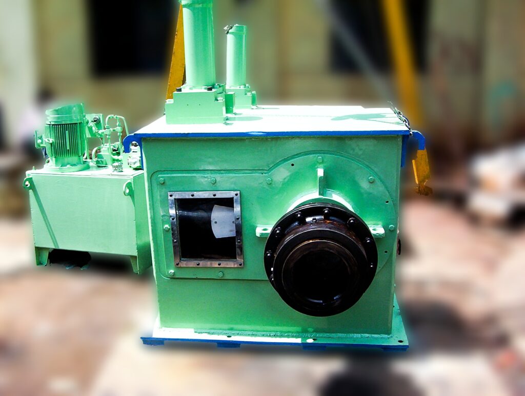
Traveling Grate/Pulsating Grate Drive
Travelling grate drive is a custom built gear unit designed to control the conveyor handling the ash released from the boiler. The drive powers up the shaft that causes the step by step rotation of the travelling grate. This product finds major applications in all boiler related fields. This improves the overall ash handling capacity of the boiler.
The drive is made up of a pawl and ratchet mechanism that is beneficial to convert rotary motion into unidirectional or linear motion. The pawl and ratchet mechanism is custom designed to change the unidirectional motion of the ratched into an oscillatory motion, between the teeth of the ratchet. This enables the shaft to rotate in a step by step way to control the linear motion of the travelling grate. The raw material entering into the boiler is fed from the top and by the time it reaches the travelling grate, it is completely burnt and the energy is consumed by the boiler.
The leftover ash travels down to the travelling grate and the step by step rotation of the shaft allows it to be evenly distributed on the travelling grate and is carried away from the boiler. The travelling grate also is specially designed and developed to cater to the industries dealing with boiler applications to efficiently handle the ash being sent out of the boiler. It can be applied in the food processing industry, steel mills, sugar industry, paper industry and many such engineering verticals where boilers are used.
The pulsating grate drive is similar in operation as compared to a travelling grate but it consists of a step design along with the grate. It is also used for similar applications as well as sorting out materials in certain cases.
Specifications
Product Features
- Drive designed for reverse motion of the travelling grate to prevent jamming
- Step by step controlled rotation of the shaft to manage the released ash
- Control and safety gauges to ensure smooth and reliable operation
- Designed and developed as per standards to suit boiler based applications
- Cooling and lubrication system to maintain pressure and efficiency of the drive.
Technical Specification
Model 1
-
- Maximum Torque: 7000 kgm
- Speed: 4-17mph
- Hydraulic working pressure: 100 bar @ 7000 kgm
- Oil Tank: 100 lit
- Cooler: 30 lpm
- Motor Capacity: 5HP + 0.5 HP
- Direction: Uni-directional movement
- Standards: ISO 2708
- Torque:
- Normal: 6000 kgm
- Maximum: 7000 kgm
- Peak: 6500 kgm
- Output Shaft dia: 125 mm
Model 2
-
- Maximum Torque: 10000 kgm
- Speed: 0-13mph
- Hydraulic working pressure: 110 bar @ 7000 kgm
- Oil Tank: 150 lit
- Cooler: 30 lpm
- Motor Capacity: 7.5HP + 0.5 HP
- Direction: Uni-directional movement
- Standards: ISO 2708
- Torque:
- Normal: 8800 kgm
- Maximum: 10000 kgm
- Peak: 90000 kgm
- Output Shaft dia: 125 mm